-
 unenlightened
10kOk, can you explain it to me ? My amazement is that this all rather predates solid state transistors.
unenlightened
10kOk, can you explain it to me ? My amazement is that this all rather predates solid state transistors. -
 wonderer1
2.4kOk, can you explain it to me ? My amazement is that this all rather predates solid state transistors. — unenlightened
wonderer1
2.4kOk, can you explain it to me ? My amazement is that this all rather predates solid state transistors. — unenlightened
It doesn't predate computers built from relays as the 'bug link' I posted shows. I would think Spencer-Brown would have been well aware of this, and wouldn't have believed himself to be presenting anything particularly novel in pointing out the possibility of memory implemented in switches.
As far as explaining... I'm not sure what you are asking me to explain. I haven't been reading along.(although I am curious about Spencer-Brown's thoughts on implementing complex math in Boolean logic) So I'm not in a position to explain much about what Spencer-Brown has to say. I could explain the workings of the flip-flop in the image I posted, but I don't have a good sense of how much background knowledge I'd need to provide, in order for you to find my explanation comprehensible. -
 Moliere
6.5kAre you looking at the 9th canon where he constructs an ever deepening series of nested a's and b's? Page 55 in my version?
Moliere
6.5kAre you looking at the 9th canon where he constructs an ever deepening series of nested a's and b's? Page 55 in my version?
If so, you just take the whole right hand expression of a & b as = r. and use J2 in reverse. — unenlightened
Yup, that's the one! Thanks.
That worked. I already became stuck on the next step. :D -- but I figured it out by going back to the demonstration of C4 and using its steps rather than the demonstrated equality between the expressions.
Then it's pretty easy to see the pattern after that: it's the same pattern as before, only being iterated upon a part of the expression in order to continue the expansion.
I can say I'm stuck with your last reported place that you're at. At least, this morning I am.
Wow, if someone implemented something like that we could have computers and an internet!
Sorry, couldn't resist. — wonderer1
This is part of my interest here -- something I've always struggled with is understanding the connection between circuits and symbols. I'm sure I don't understand how a circuit has a memory, still. -
wonderer1
2.4kI'm sure I don't understand how a circuit has a memory, still. — Moliere
I'll take a stab at trying to convey it without going into too much detail.
Frequently memories are implemented in subcircuits which have a designed in bistability. An example of a bistable system would be a coin on a table. Assuming the coin can't be stood on edge, the coin on a table will have a stable state of either showing (outputting) heads or tails, true or false, 1 or 0.
Some sort of work (flipping the coin) will need to be done in order to get the coin/table system to represent the state opposite of what it is currently representing.
The flip-flop circuit shown below is loosely analogous:
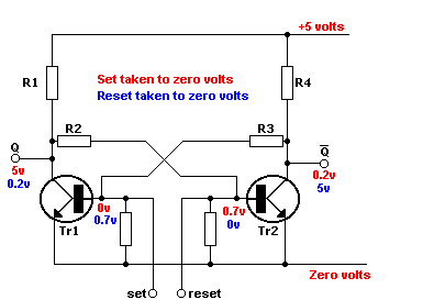
Unfortunately, the image creators were a bit sloppy in the way they used text colors (and I'm too lazy to look for a better image) so imagine the text which says "+5 Volts" and "Zero Volts" to be black. (Those parts of the circuit are 'part of the table' and stay constant. The remaining red and blue text details the two different stable conditions the subcircuit can be in - red state or blue state.
The circuit shown has two inputs S(et) and R(eset) and two outputs Q and ~Q. (Typically only one of the two outputs might be used, since as long as the system has had time to reach stability the ~Q output state is the logical inverse of the Q output state.)
The two three-terminal devices (TR1 and TR2) are transistors. The terminals that exit the transistors horizontally (to the left or right) are the control inputs to the transistors. When a control input is at 0.7 volts or greater that transistor will be on and allow current to flow in the top terminal and out the bottom terminal resulting in the output to which the transistor is connected (Q or ~Q) being pulled towards 0V (captioned as 0.2V).
Two other particularly important elements for having a flip-flop are R2 and R3. R2 and R3 represent resistors. Note that R2 connects the Q output to the input of TR2 while R3 connects the ~Q output to the input of TR1. So each output has some control of the other transistor's input. As long as S and R are not connected to anything the transistor that is turned on will keep the other transistor turned off. Simultaneously a transistor being turned off (in combination with the resistor network) causes the other transistor to be turned on. So like a coin on a table the circuit will just sit in one of the two stable states, red or blue.
The S and R inputs can be be momentarily connected to 0 Volts in order to force a change from red state to blue state and after the input which was connected to 0 Volts is disconnected the flip-flop will stay in the state it was forced into.
I'm going to leave it there for now. Let me know if that helps, or what needs more explanation.Attachment Screenshot_20230918-105513
(63K)
Screenshot_20230918-105513
(63K)
-
wonderer1
2.4kI didn't mean feedback necessarily, just the view that process might be seen as fundemental, not substance. — Count Timothy von Icarus
Yeah. Your point was recently hammered home for me on another forum by someone who wants to dichotomize everything into either physical things or abstractions, and can't understand physical processes as a category different from either.
I guess for me, feedback is important in making a system interesting, so I'm biased towards focussing on systems with feedback. -
 Count Timothy von Icarus
4.3k
Count Timothy von Icarus
4.3k
Interesting. You would think that a process view would tend to collapse the distinction between abstract and physical. Maybe not. -
Moliere
6.5kThanks! I'm going to type out what I understand from your explanation and the diagram and guess work, and I looked at this website too.
The story of a hole in a state of flow with an innumerable number of other holes towards ~Q: We start at 5 V and move through R1 to TR1 because the voltage at Q is lower than the voltage at ~Q (assuming we're already in a steady state), then we go through the unmarked resistor on the other side of the transistor, up through R3 and out ~Q. If you touch "Set" to the zero volts line than you ground the flow causing the voltage to switch over to R4-T2-R2-Q.
Based on the website I linked it looks like Q and ~Q are out of phase with one another. So the memory comes from being able to output an electrical current at inverse phases of one another? How do we get from these circuits to a logic? And the phase shift is perhaps caused by subtle manipulations of the transistor? -
wonderer1
2.4kThe story of a hole in a state of flow with an innumerable number of other holes towards ~Q: We start at 5 V and move through R1 to TR1 because the voltage at Q is lower than the voltage at ~Q (assuming we're already in a steady state), then we go through the unmarked resistor on the other side of the transistor, up through R3 and out ~Q. If you touch "Set" to the zero volts line than you ground the flow causing the voltage to switch over to R4-T2-R2-Q. — Moliere
To keep the explanation relatively simple it is easier to mostly ignore current flows and look at voltage levels in various places. However, I think it will help if I go into more detail about the type of transistor depicted in the flip-flop schematic, and the way current flows through the transistor. So to that end, let's looks at the left half of this image:
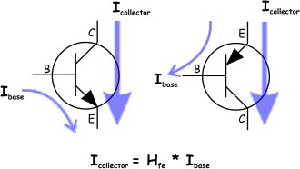
This image also helps introduce the names for the terminals of the transistor which are symbolized with B(ase) E(mitter) and C(ollector). The purple arrows indicate the way current can flow through the transistor with the width of the arrow illustrating that the current flowing into the collector is larger than the current flowing into the base. All of the current must exit out of the emitter. Typically the base current is around one hundredth of the emitter current. However, current can only flow into the collector when there is current flowing into the base. Therefore a small base current acts as an input controlling the larger collector current.
Another factor having to do with the physics of the semiconductor device that the transistor supervenes on, is the fact that the base voltage needs to get up to ~0.7 volts before current will flow into the base, and therefore before current will be able to flow through the emitter.
So to get back to simplistically modelling things in terms of the voltage levels on different wires. We can think of the transistor as a device where, when the voltage at the base of the transistor is 0.7 volts or higher, a switch is closed between the collector and the emitter, allowing current to flow through the transistor from collector to emitter.
[tl;dr]More accurately than looking at it as a switch, we might look at the path from collector to emitter as a resistor with a resistance of about 42 Ohms when the transistor is in the 'on state', and as an open circuit when the transistor is in the 'off state'. In that case, if we suppose the resistance of R1 and R4 to be 1000 Ohms, then we have an explanation for why the flip-flop schematic shows a voltage at Q of 0.2 volts for the blue state. In the blue state the 5 volts of the flip-flop power supply gets divided between the 1000 Ohm resistance of R1 and the 42 Ohm resistance of the 'on stated' TR1. In the red state the voltage at Q simply is the +5 Volts of the power supply. (Ignoring for the sake of simplicity, the the relatively low base currents flowing through R3 and R4. The ambitious reader who is into that sort of thing can assume that R3 and R4 have a resistance of 100000 Ohms, and look up linear circuit analysis, and calculate voltages out to more decimal places. However, for pragmatic purposes we can ignore current through R3 and R4, and just consider whether the voltage at the transistor bases are above or below 0.7 Volts to know whether a transistor is off or on.)
And for this discussion we can ignore the resistance of the unlabeled resistors altogether and treat them as open circuits. They are for practical details engineers need to worry about but, not of any help in looking at things in the simple voltage focused model of the flip-flop schematic.[/tl;dr]
Getting back to the flip-flop schematic...
The schematic is marked up in accordance with modelling things in terms of static voltage states where we don't need to be concerned with current flows and what happens on a dynamic basis. For now at least, we just want to look at how the circuit acts as a one bit memory. That can be understood by recognizing the fact that when the Set input is grounded to 0 Volts the red markups indicate the voltages on the wires they are near. When the Reset input is grounded the blue markups apply.
There are two other states that are of interest, which are not detailed on that schematic. These two states are the different memory states that the circuit can be in when both Set and Reset are disconnected from ground. What the voltage state of the flip-flop is, when both Set and Reset are disconnected, depends on whether Set or Reset was last tied to ground. In other words, the voltage at Q reflects the flip-flop's memory of whether Set or Reset was last connected to ground.
I'm going to have to leave off there for now. I'll respond to more of what you wrote later
Also, there is another scenario to consider, which is what happens when both Set and Reset are connected to ground yielding Q=~Q, and how Set and Reset being disconnected from ground simultaneously is like flipping a coin. But as Q=~Q might suggest, that's a state that is best avoided for sound logic. -
Moliere
6.5kHrm! That helps me understand the feedback part very well -- so thank you again for taking the time. When Set is grounded the voltage from R3 no longer gives the voltage necessary for the transistor to be in the "on" state, but the parallel circuit through R2 does so the circuit flips over to Tr2. Since Tr1 is now off that means 5V goes to Q as the path of least resistance. The same holds for reset and the blue state.
And that helps me understand how it has a memory -- when you come back to it it'll be in one state or the other, so there are two possible states for the circuit to be in when at equilibrium.
And I can now see how they are switches thanks to your explanation, which was a bit of a mystery to me before. -
wonderer1
2.4kThat helps me understand the feedback part very well -- so thank you again for taking the time. When Set is grounded the voltage from R3 no longer gives the voltage necessary for the transistor to be in the "on" state, but the parallel circuit through R2 does so the circuit flips over to Tr2. Since Tr1 is now off that means 5V goes to Q as the path of least resistance. The same holds for reset and the blue state. — Moliere
Very good! :up:
I'll respond to the rest of your previous post later today. -
wonderer1
2.4kBased on the website I linked it looks like Q and ~Q are out of phase with one another. So the memory comes from being able to output an electrical current at inverse phases of one another? How do we get from these circuits to a logic? And the phase shift is perhaps caused by subtle manipulations of the transistor? — Moliere
Phase isn't a particularly useful concept for thinking about the relationships between Q and ~Q. In the case where both Set and Reset are grounded, both Q and ~Q will be at 5 Volts rather than one being at 5V and the other being at 0.2 Volts. Also, when considering the transitions from one state to another things get messy for a time and thinking of Q and ~Q as having a phase relationship breaks down.
As for, "How do we get from these circuits to a logic?"...
So with a flip-flop we can use as a one bit memory, we have what we can think of as a logical variable. Additional circuitry can take the Q output of multiple flip-flops and perform logical operations. The result of the logical operation can then be stored in another flip-flop, for use at a later time.
At this point it is pragmatic to jump up a level in abstraction and think in terms of logic gates instead of transistor circuits. So we can have an AND gate and brush consideration of transistors, resistors, and power supplies under the rug. We can simply think of an AND gate as a device with two inputs which treat voltages above 2.5 Volts as a logical 1 (true), voltages below 2.5 Volts as a logical 0 (false), and output the logically appropriate voltage level on the output.
The following image shows schematic symbols for logic gates of various kinds and their truth tables:

Such logic gates can be strung together to yield whatever logical function is needed. For example a one bit adder:
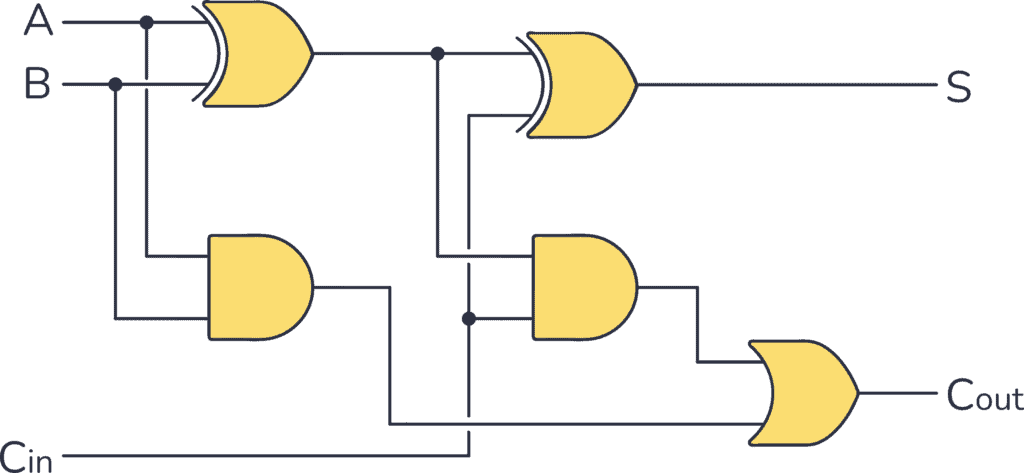
A and B could be the outputs of two flip flops representing the two bits to be summed. Cin represents "carry in" and can be connected to the "carry out" of another adder. S will have an output logic level representing the sum of A and B given the state of Cin. Cout will have an output level which can be connected to the Cin of a different adder.
By connecting such logical blocks together we can create something useful. For example we could have three 32 bit registers. (With each register just being a collection of 32 flip-flops.) Two of those registers could have 32 bit binary numbers that we want to add together. The third register could have its flip-flop inputs connected to the S outputs of a 32 bit adder chain and thus we would have the ability to take two stored 32 bit numbers and add them and store the sum in the output register.
Now so far I've glossed over the dynamics of changing states. That is much too complicated to try to cover in any detail. With digital logic, typically a 'clock' is used in order to be able to ignore the short term dynamic transitions of flip flops and logic gates from one stable state to the next.
The SR flip-flop schematic I showed is about as bare bones as a flip-flop can get. The flip-flops in a microprocessor are typically more complex D flip-flops which have a D(ata) input terminal and a CLOCK input. D flip-flops work by changing their output state (Q) to match the D input state when the clock signal transitions from a logic 0 to a logic 1. So with all of the flip-flops tied to the same clock signal, all of the transitioning can be synchronized. As long as the clock frequency is slow enough, all of the dynamic transitioning that occurs after the last clock edge has time to settle to a stable state before the next clock edge. -
Moliere
6.5kThis is great. Thanks again for taking the time to write out these explanations.
At this point it is pragmatic to jump up a level in abstraction and think in terms of logic gates instead of transistor circuits. — wonderer1
Of course, though, this is what I want :D
I think what I'm wanting to settle, for myself, is whether or not the circuits are in turn being interpreted by us, or if they are performing logical operations. What makes Q and ~Q different other than one is on the left side, and the other on the right side? Do we just arbitrarily choose one side to be zero and the other side to be 1? Or do the logical circuits which have a threshhold for counting do it differently?
To my mind the circuit still doesn't really have a logical structure anymore than a stop light has the logical structure of Stop/Go without an interpretation to say "red means stop, green means go". So are we saying "Q means 1, and ~Q means 0"? -
wonderer1
2.4kI think what I'm wanting to settle, for myself, is whether or not the circuits are in turn being interpreted by us, or if they are performing logical operations. — Moliere
I'm not clear on what you want clarification of, but let my respond to the rest of your post and then let me know what might still be unaddressed.
What makes Q and ~Q different other than one is on the left side, and the other on the right side? Do we just arbitrarily choose one side to be zero and the other side to be 1? Or do the logical circuits which have a threshhold for counting do it differently?
To my mind the circuit still doesn't really have a logical structure anymore than a stop light has the logical structure of Stop/Go without an interpretation to say "red means stop, green means go". So are we saying "Q means 1, and ~Q means 0"? — Moliere
The SR f!ip-flop circuit is symmetrical, so it is somewhat arbitrary which output is chosen to be Q and ~Q. However, the Set pin is defined as the input that can cause Q to produce a 1 (5V) output. So one could swap Q and ~Q, but to be consistent with the conventions for SR flip-flops one would also need to swap which input is labeled S and which R. So like the stoplight it is a matter of convention.
Also, flip-flops themselves don't perform logical operations. They just serve as memories that can be used to provide inputs to logic gates (or combinations thereof), and store outputs from logic gates. -
Moliere
6.5kThe SR f!ip-flop circuit is symmetrical, so it is somewhat arbitrary which output is chosen to be Q and ~Q. However, the Set pin is defined as the input that can cause Q to produce a 1 (5V) output. So one could swap Q and ~Q, but to be consistent with the conventions for SR flip-flops one would also need to swap which input is labeled S and which R. So like the stoplight it is a matter of convention. — wonderer1
OK, cool. That was what I was thinking, but realized I didn't know. Given the topic of the book -- a kind of proto-logic prior to logic, or from which logic emerges (with a practical basis in sorting out electrical work and inventing a logic for that) -- it seemed important to me.
Also, flip-flops themselves don't perform logical operations. They just serve as memories that can be used to provide inputs to logic gates (or combinations thereof), and store outputs from logic gates.
Got it. This is a memory, and not an operating circuit. So it holds a 1 or a 0, and it's by convention that a side of the flip-flop is treated as a 1 and the other as 0, and it behooves us to be consistent because then we can start doing cool things like reducing our number system to binary and having circuits perform operations faster than we can. -
Moliere
6.5kFor Laws of Form Relays may be the better bit of technology to look at, though they function the same as the transistor. Looking through wikipedia at all this stuff I noticed the paragraph at the end sounded pretty similar to the basic operation in Laws of Form:
Latching relays require only a single pulse of control power to operate the switch persistently. Another pulse applied to a second set of control terminals, or a pulse with opposite polarity, resets the switch, while repeated pulses of the same kind have no effects. Magnetic latching relays are useful in applications when interrupted power should not affect the circuits that the relay is controlling. — wiki -
Moliere
6.5kCool. I think that's enough of the concrete side of things for me to feel like I have a footing again. Thank you again for your explanations @wonderer1.
I'm really just inching along in this chapter. Every page presents a problem. Now I feel I have a handle on how we get to infinite expansions but I'm stuck on Re-entry on page 56-57 (I realize now before I was citing the pdf pages rather than the book pages. These are the book pages)
So I looked back at the rule of dominance because that's how we're meant to determine the value of infinitely expanding functions for the various values of a or b being either m or n. I went back to the rule of dominance because it seemed like basic substitution didn't work. But as I apply the rule of dominance I'm getting different values at each step of E1 in chapter 11.
=
= (1)
= (2)
= (3)
= or (4)
So I've tried three different things in trying to get all the equations to equal what they state here:
1) substituting the marked state for m and the unmarked state for n while expanding each instance of "f" with one more iteration so you'd have, in the case of (1): m-cross-m-cross-m-cross-m-cross. Since you have an even number of crosses all embedded within one another you get n -- the unmarked state. But then if I try this on (2): m-cross-n-cross-m-cross-n-cross: we have an even number of crosses embedded within one another so it should reduce to the unmarked state, but (2) reduces to the marked state.
2). The rule of dominance. You begin at the deepest depth which would be "f" in each case and alternate putting m or n next to the next depth-level. So starting with (1):
(1)
(1.1)
(1.2)
(1.3)
(1.4)
(1.5)
and by the rule of dominance I get m because that's what sits in the pervading space.
But that's not the right way to apply the rule, then, since we must get n from the procedure for (1). Which brings me to:
3) Substitution from the Sixth Cannon where :
=
=
But then for (3) I get m, because n-cross equals m and m-cross equals n and that leaves m after substituting.
While writing this out I came up with a 4th possibility: just mark the next m or n, as you'd do with the rule of dominance, and take the value in the outer space. But then (5) is equal to m, and not m or n, except in a fancy way of interpreting "or" which I don't think is what's going on.
So, as I said, I'm inching along and every page presents a problem. :D This is as far as I got this morning. (EDIT: Changed the number-names of each step to conform with the thread) -
unenlightened
10kI'm struggling to see what you are trying to do there. you want to be simplifying, not complicating.
You cannot begin at the deepest level because re-entry makes it infinite. So you simply evaluate each case as it stands, and the f drops out in every case except the last one, where everything else drops out. It is because the f doesn't drop out that there are still the 2 possibilities for its value.
Wait, I think i see what you are doing - treating each line as an equation, and then substituting the right back in for f.
You don't want to do that! Each line is a result for a combination of an and b. There is no working shown, and almost none to do. so for (2):–
=
and the re-entered f can be ignored. -
Moliere
6.5kWait, I think i see what you are doing - treating each line as an equation, and then substituting the right back in for f. — unenlightened
Yup. The first line states what f is and that's how I was treating it.
You don't want to do that! Each line is a result for a combination of an and b. There is no working shown, and almost none to do. so for (2):– — unenlightened
=
and the re-entered f can be ignored.
Cool. So with this solution the trouble I have is with (4). n-cross-m-cross is three crosses and so should equal m, but (4) equals n.
Right before these lines GSB states:
We can now find, by the rule of dominance, the values which f may take in each possible case of a,b.
And the rule of dominance doesn't care about the infinite depth it cares about S-sub-0, the pervading space. For solution 2 I was treating "m" as the marked space and putting an "m" then "n" alternatively as I filled out the expression. For solution 4 I'm ignoring m and n and simply marking S-sub-0 with the next letter that follows. That works for (1) through (4), but (5) it would simply be equal to "m" rather than m or n by this procedure.
But this is me explaining my failed evaluations trying to figure out how to get to a successful one. (I've actually typed out a few of these puzzlers before only to find the solution at the end and delete the puzzler in favor of the solution... but this time I was still stuck at the end of my post)
And if I follow GSB's outline for (5) and apply it to (4) I'd say we have two expressions that evaluate to m or n -- because if f equals m, then you get mn-cross-m-cross, which is m-cross-m-cross, which is an even number of embedded crosses that gives you n, but if f equals n then you get nn-cross-m-cross, which is an odd number of embedded crosses so you get m.
The other three work out that way.
Basically I'm treating all 5 as test cases for understanding how to evaluate an expression's value which has re-entry and each time I try to use one of these solutions one of the equations comes out differently from what's written in the book.
So these are my failed evaluations which I'm sharing because this time by typing it out I haven't figured out how to do it right. -
unenlightened
10kYou're making the very simple, complicated. these are not equations, but evaluations of f for all the possible values of a & b. the right hand side in each case is the result of simplifying the left
(4).
= (because n= . )
= f.
And this means that when a = n and b = n, f can = n or m. And thus we have the shape of the flip flop circuit. -
Moliere
6.5kYou're making the very simple, complicated. these are not equations, but evaluations of f for all the possible values of a & b. the right hand side in each case is the result of simplifying the left — unenlightened
Ahhhhh.... OK I think it clicked now. I figured out my mistake. I was treating "m" in (3) as embedding the crosses to its left, but in fact it's alongside the crosses rather than embedded and so I was just doing the evaluation incorrectly. Then upon finding the wrong answer I tried to come up with various other possible ways to evaluate, which I've already shared at length, and now I see how they simplify.
So due to Theorem 2 I can easily simplify (1) and (3) -- an empty cross next to any combination of expressions simplifies to the empty cross, and m is an empty cross. (within the cross, so cross-cross = the unmarked state)
That leaves (2) and (4).
For (2):
Let f = m, and mm = m, therefore we are left with the marked state.
Let f = n, and nm = m, and we have the same.
But for (4) when we do this the evaluation comes out m or n.
Thanks for the help. I made a small mistake along the way and it resulted in a lot of confusion. -
Moliere
6.5kI am a moth jumping from light to light, but I usually come back around.
This morning I find myself going back. In particular as I proceeded I started to pick up on a pattern in the writing: between theorems and conclusions.
Going to Chapter 4: Theorems are general patterns which can be seen through formal considerations of the Initials. Also axioms are used. In going back to get a better feel for the distinctions between these terms I'm also picking up on that Canon is never formally defined -- it's like a Catholic Canon in its function. Also I'm picking up on why identity is the 5th theorem -- if the calculus was inconsistent then you could come up with x =/= x. And, going back over, I'm starting to see the significance of theorem 7 -- it's what let's us build a calculus through substitution, which theorem's 8 and 9 provide the initials for that calculus in chapter 5.
This is all inspired by the paragraph immediately where I left off:
We may take the evident degree of this indeterminacy to
classify the equation in which such expressions are equated.
Equations of expressions with no re-entry, and thus with no
unresolvable indeterminacy, will be called equations of the
first degree, those of expressions with one re-entry will be called
of the second degree, and so on.
It is evident that Jl and J2 hold for all equations, whatever
their degree. It is thus possible to use the ordinary procedure
of demonstration (outlined in Chapter 6) to verify an equation
of degree > 1. But we are denied the procedure (outlined
in Chapter 8) of referring to the arithmetic to confirm a demonstration
of any such equation, since the excursion to infinity
undertaken to produce it has denied us our former access to a
complete knowledge of where we are in the form. Hence it
was necessary to extract, before departing, the rule of demonstration,
for this now becomes, with the rule of dominance,
a guiding principle by which we can still find our way.
And reviewing back up to Chapter 5 is about as far as I got this morning. I'm attempting to disentangle the procedures of Chapter 6 from Chapter 8 to give myself a better understanding of what's missing and needed to understand the next bits in Chapter 11. -
unenlightened
10kAlas, I find myself stuck again at the same place as last time. I think i understand how re-entry introduces time and square wave oscillation, and sort of how more than one re-entry is required for two oscillating values to cancel out to produce an imaginary value. But then it all becomes incomprehensible circuitry, and I cannot find the reality of the theory or the theory of reality any more.
Halfway down P.65 at "Modulator function" I just stop following. E4 is just too complicated and too big a jump for me, and I cannot recognise its translation into what is looking much like a simplified circuit diagram. I can just about see the translation of the example without re-entry bottom of P.66 and top of P.67. I have been hoping that someone could help me out at this point with the translation of E4, and then its further implementation using imaginary values. -
Moliere
6.5kI'm still crawling my way there. This morning I didn't have time to do my little bit of philosophy to warm up the mind. Hopefully with two of us we can guess our way through.
-
Moliere
6.5kFrom Chapter 8, p43-44:
A consequence is acceptable because we decided the rules.
All we need to show is that it follows through them.
But demonstrations of any but the simplest consequences
in the content of the primary arithmetic are repetitive and
tedious, and we can contract the procedure by using theorems,
which are about, or in the image of, the primary arithmetic.
For example, instead of demonstrating the consequence above,
we can use T2.
T2 is a statement that all expressions of a certain kind, which
it describes without enumeration, and of which the expression
above can be recognized as an example, indicate the marked
state. Its proof may be regarded as a simultaneous demonstration
of all the simplifications of expressions of the kind it
describes.
But the theorem itself is not a consequence. Its proof does
not proceed according to the rules of the arithmetic, but follows,
instead, through ideas and rules of reasoning and counting
which, at this stage, we have done nothing to justify.
Thus if any person will not accept a proof, we can do no
better than try another. A theorem is acceptable because what
it states is evident, but we do not as a rule consider it worth
recording if its evidence does not need, in some way, to be
made evident. This rule is excepted in the case of an axiom,
which may appear evident without further guidance. Both
axioms and theorems are more or less simple statements about
the ground on which we have chosen to reside.
Since the initial steps in the algebra were taken to represent
theorems about the arithmetic, it depends on our point of view
whether we regard an equation with variables as expressing a
consequence in the algebra or a theorem about the arithmetic.
Any demonstrable consequence is alternatively provable as
a theorem, and this fact may be of use where the sequence of
steps is difficult to find.
Perhaps a way to put it, and to go back to an earlier distinction: Theorems are statements in the meta-language about what we can do in the object-language, and consequences are demonstrations within the object-language.
And the statement of GSB's I'm trying to understand:
But we are denied the procedure (outlined
in Chapter 8) of referring to the arithmetic to confirm a demonstration
of any such equation, since the excursion to infinity
undertaken to produce it has denied us our former access to a
complete knowledge of where we are in the form.
To use arithmetic we have to have a complete knowledge of where we are in the form, it seems, but the calculus manages fine because, well, we are dealing with variables at that point?
Something subtle in there that I'm not fully picking up. -
Moliere
6.5kOK I think all that GSB is saying in that paragraph, in simplified terms, is that re-entry doesn't allow us to use the arithmetic to solve for the value of an expression because re-entry creates an infinite sequence which doesn't allow us to substitute the marked or unmarked state for all cases within an expression (given that the expression is infinite). The part that makes that confusing to me is that the proofs for the Conclusions in Chapter 6 rely upon that same move -- the only way this makes sense is that we can use the initials for the parts of an expression which are "presented", but re-entry indicates a "...and so on" which is unspecified and so it becomes impossible to simply substitute for all cases of a particular variable the marked or unmarked state. E1 in Chapter 11 shows there is at least one case where an expression with re-entry simplifies to either the marked or unmarked state while attempting to utilize the arithmetic in this way to substitute and simplify, and so re-entry denies Chapter 8 as a set of theorems that rely upon being able to specify where one is at in the form.
I'm still a little confused about why this doesn't effect Chapter 6, but I think I understand why Chapter 8 is denied at least. And I'm ready to push on as well.
So the flip-flop circuit gives us a reason to posit imaginary values -- at this point I think "imaginary" is a bit of a term of art. So far the mathematics presented have been reliant upon forms and their inter-substitutibility. But here we have a form that, just like imaginary numbers in our everyday algebra, demands another number. (or, in this case, form, since numbers aren't really a part of the domain of interest) -- in a way we have to look at "p" in Figure 1 as having both the marked and unmarked state, and so we introduce imaginary values to indicate "the value of this expression is dependent upon the value of a function, and the value of a function depends upon time -- it is either the marked or unmarked state, but the calculus (with the assistance of the arithmetic, at least) cannot give you the answer at this point"
Also I think I understand what GSB is on about with respect to the oscillator function -- in p-cross-p if p is marked then the function is marked, and if p is unmarked then the function is unmarked. So there are some functions which even as they oscillate they are still continuously valued.
.... well, and that's as far as I got this evening. :D
Looking at E4 at this point I think we have to be able to follow along with a given expression's oscillation patterns, sort of like what I did with p-cross-p in the above, such that we can tell, over time, how often it will be marked or how often it will be unmarked or if it will always be one or the other. -
unenlightened
10kOK I think all that GSB is saying in that paragraph, in simplified terms, is that re-entry doesn't allow us to use the arithmetic to solve for the value of an expression because re-entry creates an infinite sequence which doesn't allow us to substitute the marked or unmarked state for all cases within an expression (given that the expression is infinite). — Moliere
I think that's right.
We see, in such a case, that the theorems of representation no longer hold, since the arithmetical value of e' is not, in every possible case of a, b, uniquely determined. — P 57
Reentry produces kind of fractal/recursive infinity. The last case of P.56 that you had problems with produces an indeterminate value, and this means that when there is reentry, the calculus cannot always reach a determinate answer. Could be flip, or could be flop for example, or could be oscillating. The algebra still works, but the re-entered expression 'f' cannot be substituted by mark and then by no mark and then, 'there is no other case'; now there are other cases.


Welcome to The Philosophy Forum!
Get involved in philosophical discussions about knowledge, truth, language, consciousness, science, politics, religion, logic and mathematics, art, history, and lots more. No ads, no clutter, and very little agreement — just fascinating conversations.
Categories
- Guest category
- Phil. Writing Challenge - June 2025
- The Lounge
- General Philosophy
- Metaphysics & Epistemology
- Philosophy of Mind
- Ethics
- Political Philosophy
- Philosophy of Art
- Logic & Philosophy of Mathematics
- Philosophy of Religion
- Philosophy of Science
- Philosophy of Language
- Interesting Stuff
- Politics and Current Affairs
- Humanities and Social Sciences
- Science and Technology
- Non-English Discussion
- German Discussion
- Spanish Discussion
- Learning Centre
- Resources
- Books and Papers
- Reading groups
- Questions
- Guest Speakers
- David Pearce
- Massimo Pigliucci
- Debates
- Debate Proposals
- Debate Discussion
- Feedback
- Article submissions
- About TPF
- Help
More Discussions
- Other sites we like
- Social media
- Terms of Service
- Sign In
- Created with PlushForums
- © 2026 The Philosophy Forum